


Description
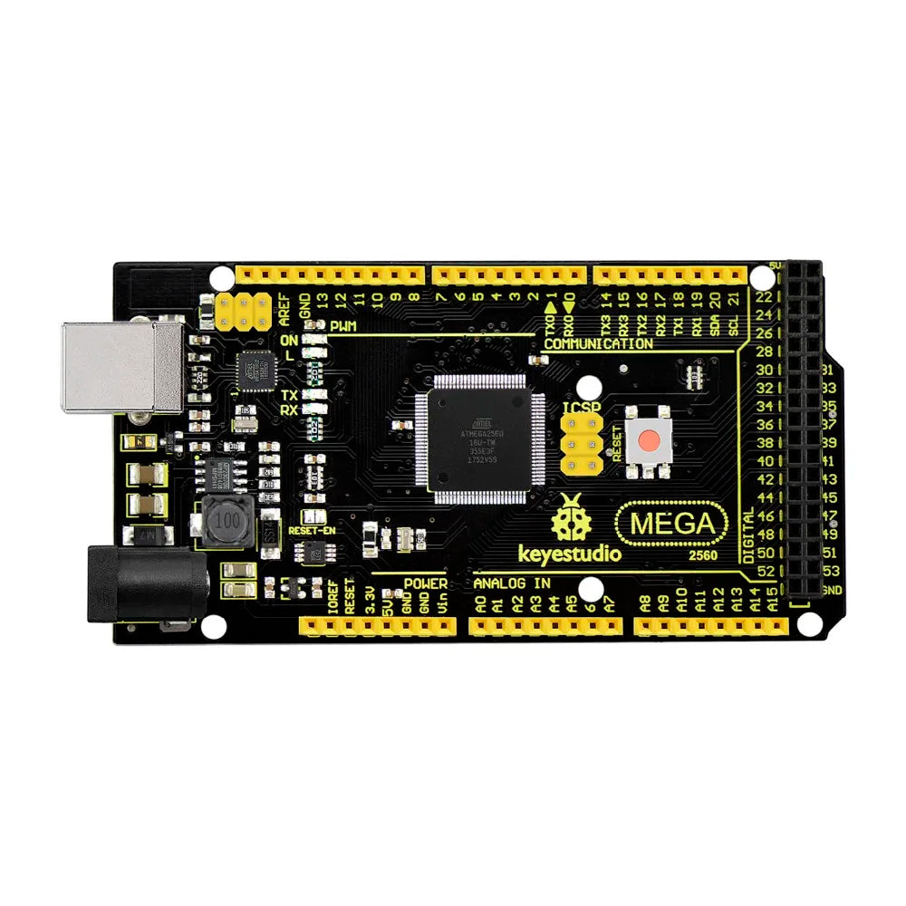
The Keyestudio Super Mega 2560 R3 Development Board is built around the ATMEGA2560-16AU microcontroller, fully compatible with the Keyestudio Mega 2560 R3 and Arduino Mega 2560 REV3. It offers 54 digital I/O pins (15 PWM-capable), 16 analog inputs, 4 hardware UARTs, a 16 MHz crystal oscillator, USB connectivity, power jack, dual ICSP headers, and a reset button. Equipped with a bootloader, it allows direct programming via USB without an external programmer. Power options include USB, an external DC jack (7-12V), or Vin/GND headers, providing flexible and robust support for complex projects.
The Keyestudio Super Mega 2560 R3 Development Board features an upgraded MP2307DN voltage regulator, delivering a 5V output with a drive current of up to 2A when powered externally—double the 1A provided by the NSP1117 regulator on the standard Mega 2560 R3. Designed for complex projects, it offers 54 digital I/O pins, 16 analog inputs, and ample memory space, making it ideal for applications like 3D printing and robotics that demand higher power and expanded capabilities.
Specifications
| Microcontroller | ATMEGA2560-16AU |
|---|---|
| Operating Voltage | 5V |
| Input Voltage (recommended) | DC7-12V |
| Digital I/O Pins | 54 (D0-D53) |
| PWM Digital I/O Pins | 15 (D2-D13; D44-D46) |
| Analog Input Pins | 16 (A0-A15) |
| DC Current per I/O Pin | 20 mA |
| DC Current for 3.3V Pin | 50 mA |
| Flash Memory | 256 KB of which 8 KB used by bootloader |
| SRAM | 8 KB |
| EEPROM | 4 KB |
| Clock Speed | 16 MHz |
| LED_BUILTIN | D13 |

 |
Digital I/O
Arduino MEGA has 54 digital input/output pins (of which 15 can be used as PWM outputs). These pins can be configured as digital input pin to read the logic value (0 or 1). Or used as digital output pin to drive different modules like LED, relay, etc. |
 |
GND
Ground pins |
 |
AREF
Reference voltage (0-5V) for analog inputs. Used with analogReference(). Configures the reference voltage used for analog input (i.e. the value used as the top of the input range). |
 |
SDA
IIC communication pin |
 |
SCL
IIC communication pin |
 |
ICSP (In-Circuit Serial Programming) Header
the AVR, an Arduino micro-program header consisting of MOSI, MISO, SCK, RESET, VCC, and GND. Connected to the ATMEGA16U2-MU. When connecting to PC, program the firmware to ATMEGA16U2-MU. |
 |
USB Connection
Arduino board can be powered via USB connector. |
 |
D13 LED
There is a built-in LED driven by digital pin 13. When the pin is HIGH value, the LED is on, when the pin is LOW, it's off. |
 |
ATMEGA 16U2-MU
USB to serial chip, can convert the USB signal into serial port signal. |
 |
TX LED
Onboard you can find the label: TX (transmit) |
 |
RX LED
Onboard you can find the label: RX(receive ) |
 |
Crystal Oscillator
How does Arduino calculate time? by using a crystal oscillator. |
 |
Voltage Regulator
Convert an external input DC7-12V voltage into DC 5V, then switch DC 5V to the processor and other components. Output DC 5V, the drive current is 2A. |
 |
DC Power Jack
Arduino board can be supplied with an external power DC7-12V from the DC power jack. |
 |
IOREF
This pin on the board provides the voltage reference with which the microcontroller operates. A properly configured shield can read the IOREF pin voltage and select the appropriate power source or enable voltage translators on the outputs for working with the 5V or 3.3V. |
 |
RESET Header
Connect an external button to reset the board. The function is the same as reset button. |
 |
Power Pin 3V3
Provides 3.3V voltage output |
 |
Power Pin 5V
Provides 5V voltage output |
 |
Vin
You can supply an external power input DC7-12V through this pin to Arduino board. |
 |
Analog Pins
Onboard has 16 analog inputs, labeled A0 to A15. |
 |
RESET Button
You can reset your Arduino board, for example, start the program from the initial status. You can use the RESET button. |
 |
ICSP (In-Circuit Serial Programming) Header
the AVR, an Arduino micro-program header consisting of MOSI, MISO, SCK, RESET, VCC, and GND. |
 |
Microcontroller
Each Arduino board has its own microcontroller. You can regard it as the brain of your board. |
 |
Power LED Indicator
Powering the Arduino, LED on means that your circuit board is correctly powered on. If LED is off, connection is wrong. |
Payment & Security
Your payment information is processed securely. We do not store credit card details nor have access to your credit card information.